What are Jumpers?
Jumpers are a type of switch used to quickly adjust specific functions on a circuit board. The principle behind inserting or removing jumpers involves physically changing the position of the jumper or solder/desoldering the two copper pad. Thereby altering the circuit’s connection. This allows for the implementation of functions similar to adding a switch to a fixed circuit design. Jumpers used to be quite common on early days circuit boards, but their usage has decreased in recent years due to the miniaturization of electronic circuits. To facilitate various development applications on this development board, we have incorporated some interesting adjustable jumper designs for hobbyist and makers to fully unleash the potential of the BOBODUINO!
On the front side of the board, we have implemented jumpers that can be directly plugged and unplugged by hand. Through these jumpers, you can switch the voltage potential between 5V and 3.3V. On the back side of the board, solder-type jumpers can be used to adjust the battery charging current (Bat. charge current, JP1/JP2), enable automatic reset for serial communication (Auto-reset, JP3), enable pin control reset (Enable A2 reset control, JP4), and enable or disable the 3.3V linear regulator (Enable 3.3V LDO, JP5). Lastly, there is a power-saving feature for the 5V output (JP6). In the following article, we will provide a brief overview of all these specific functions.

5V/3.3V Selection Jumper
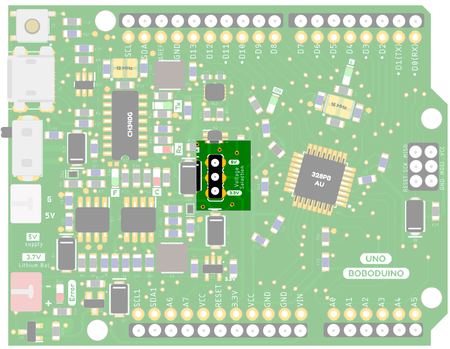
Front, Center
The 5V/3.3V switching jumper design on the front side of the board has been designed for users to quickly adjust the voltage on the board. Sometimes, you may need to connect different types of sensors, and you might happen to have a sensor that can only operate at either at 3.3V or 5V. In such case, you’ll find this jumper design very useful. Adjusting the board’s voltage become super easy! Before the adjustment, please disconnect any external power source, pull the green jumper and place it in the marked positions for 5V or 3.3V for your own need. You might be curious about the potential state when the jumper is not connected. The answer is: the left-side power management circuit will not be able to supply power to the right-side ATmega328Pb chip, meaning the 328PB McU will be in a state with no power.
5V/3.3V adjusting jumper
🔌 Disconnect the external power source
To avoid the sudden change in voltage (voltage spike) when changing the jumper, remember to disconnect the external power source before inserting or removing jumpers.
How to Adjust Solder-Type Jumpers
Solder-type jumpers require soldering techniques to open or close specific loops on the circuit board. Compared to plug-and-play jumpers, solder-type jumpers are smaller in size and offer better stability because they are connected through soldering. However, the drawback is that they require tools like a soldering iron and solder when you want to change the connection state.
To connect solder-type jumpers, you can use solder to bridge the connection between the two ends of the copper pad. When you need to disconnect them, apply a small amount of soldering flux to the solder joints and use a soldering iron along with a desoldering wick to remove the solder beads on the pad surface. This allows you to disconnect the connection between the two pads.
After you desolder the two pads, remember to check the connectivity with the electrometer.

Battery Charging Speed Adjustment (Bat. charge current, JP1/JP2)
Backside, solder-type jumpers
BOBODUINO utilizes the TP5400 charging chip, which can provide a maximum charging current of up to 1A. Since users may acquire LiPo batteries with different capacities from various sources, we have incorporated a design that allows you to adjust the charging speed by manipulating these jumpers. When both JP1 and JP2 are disconnected, the battery charging IC will charge the battery at the current of 80 mA. This charging current is suitable for most small to medium-sized batteries. When JP2 is connected, the battery will charge at 500 mA, and when JP1 is connected, the charging current will be reach to nearly 1A. For safety purpose, we recommend users to charge the battery at 1/2C or lower. We will explain how to calculate this in the column below.
Jumpers at back

⚠️ Special Note on Charging Speed
Use 1/2C or lower is better for safety battery charging…
Charging speed doesn’t necessarily need to be set to a higher current; it should be based on the recommended charging parameters provided by the manufacturer of the battery. In general, we recommend using a 1/2C or lower charging speed for most batteries. But what does 1/2C mean? Let’s say you’ve purchased a 1000mAh battery. When charging the battery at a rate of 1A, it takes approximately one hour to fully charge. However, if you charge the battery at a 1/2C rate, you’ll be using a charging current of 500 mA. Since different batteries are designed to operate at various optimal charging speeds, and mishandling lithium batteries can pose potential risks, we recommend selecting batteries certified by your local government department and equipped with lithium battery protection circuits. Additionally, it’s good practice to understand the recommended charging speed for the battery you’ve purchased. Even if the official recommendation is a 1C charging speed, it’s still advisable to use a lower charging speed, such as 1/2C or 1/3C, for better safety
Auto-reset (JP3)
Backside, top right corner
If you’ve been using Arduino for a while, you may have noticed something magical. Let’s say you’ve had your board connected to your computer for some time. The moment you open up the Serial Monitor, you’ll notice that the power indicator LED suddenly blinks, and your board enters the reset state. Now, imagine you’re using your microcontroller board to control a robotic arm with many RC servo motors. This automatic restart when connecting to the Serial Monitor may cause your servo motors to move abruptly due to the board restarting. Sometimes, this is not what we want 🙁
The automatic restart feature when connecting to the Serial Monitor is designed by the official Arduino to make it easier for most users to upload code. However, in some specific applications (such as the robotic arm example we mentioned earlier), it can lead to unwanted effects. On our BOBODUINO board, this issue can be easily resolved. You just need to desolder the jumper labeled JP3 in the top right corner on the back of the board. Once you’ve done this, your board won’t automatically restart when you connect to the Serial Monitor. Quite funny, isn’t it? But wait, it also won’t automatically restart the next time you want to upload your code. We will illustrate how to upload the code after you have desoldered JP3.
💡 JP3 Default Setting
In the factory default state, the jumper on JP3 is initially soldered (connected) together because this design makes it more convenient for most of users to uploading programs. When uploading a program, there is no need to press the reset button first, which is very convenient!
💡 Uploading Programs After Desoldering
After desoldering JP3, you will need to press and hold the reset button before uploading a program. Release the reset button at the moment the Arduino IDE displays “uploading…” It’s not that difficult, just a bit more cumbersome. After a few tries, you should be able to achieve a 100% success rate I promise. (You can think of it as a little game to train your reaction speed)
A2 Restart (Enable A2 reset control, JP4)
Backside, bottom left corner
Backside, bottom left corner
In certain situations, you may wish to incorporate a design that automatically restarts the BOBO board, somewhat akin to when I encounter a problem and decide to reboot myself (which suddenly reminded me of the useless mechanic box). In such cases, a relatively straightforward method is to utilize Pin Control Auto-Reset, which can be implemented as follows:
- Solder JP4 jumper to establish a connection between pin A2 and the reset pin of the ATmega328PB chip.
- Put the code like this in the condition when you want to restart the board:
//Reset the board when something happened...
if(…){
   digitalWrite(A2, LOW);
   delay(200); //Delay for a while for the board to reset
}
In this way, it is easy to generate the effect of restarting Boboduino using the A2 pin when encountering a certain situation.
It is important to note that the A2 pin needs to be pulled to a high level during initialization in the setup() function; otherwise, it may cause the board to endlessly reboot after startup. If this situation occurs, you will need to incorporate something into the code like this to fix this bug:
void setup() {
   //Initiate the A2 pin and pull it to high...
   pinMode(A2, OUTPUT);
   digitalWrite(A2, HIGH);
}
Turn off the 3.3V linear regulator (Enable 3.3V LDO, JP5)
On the backside, in the middle.
On the Boboduino board, there is an AP2112 3.3V chip that provides power to the board. Since the AP2112 is a linear regulator, and the default power supply system on the board continuously provides power to this chip, some users may not require the 3.3V power or may be concerned about unnecessary power consumption. In this case, you can choose to desolder the jumper on the backside of the board. Doing so will disable the 3.3V power supply, rendering the 3.3V pin unusable. This can be beneficial if you want to conserve power when operating on battery. In fact, based on our testing results, the AP2112 chip consumes very little power in the absence of a load. According to the datasheet, the AP2112’s quiescent current is extremely low, approximately only 55 µA. This means that in most applications, we can disregard the presence of this LDO linear regulator. However, if you have significant concerns, you can choose to desolder and deactivate it.
💡 Quiescent Current
Quiescent current is a term used in electronics to describe the current flowing through a specific device or circuit when it is idle or inactive. This current represents the minimum amount of current required to maintain basic operation of the device or circuit when it is not actively performing its primary function.
Part of AP2112 datasheet

Power saving mode(Power save mode, JP6)
Back side, upper left corner
The RT6150BGQW, which provides a 5V power supply, is an interesting Buck-boost converter (I like to call it a BB converter). This means that this chip can increase the voltage when the input voltage is lower and decrease the voltage when the input voltage is higher. The advantage of this chip is its compatibility with various external power source conditions. The RT6150BGQW also has a power-saving mode that can be utilized. According to the official datasheet, in power-saving mode, the quiescent current is around 60 µA, and the quiescent current in high-frequency mode may need to be measured. The JP6 on the Boboduino development board that comes from the factory is not soldered (meaning it operates in power-saving mode in the default setting). If there is a higher current demand in your application, you can connect JP6 to disable the power-saving mode. (In reality, whether the power-saving mode is enabled may not be very noticeable in most application scenarios).
The following excerpt is from the RT6150BGQW datasheet:
The device includes two N-MOSFET switches and two P-MOSFET switches for high efficiency operation. Switching frequency is set at 1MHz to reduce the external component size. Quiescent current is only 60 μA in Power Save Mode (PSM), maximizing battery life in portable applications. PSM operation is user controlled and can be enabled by driving the PS pin low. If the PS pin is driven high, then fixed frequency switching is enabled.